High volume GD&T of single parts
Inspections of BIW individual parts are performed manually or automatically at various stages throughout the manufacturing process. Either tactile or non-contact sensors can be selected, while measured data is compared with CAD data to check part quality.

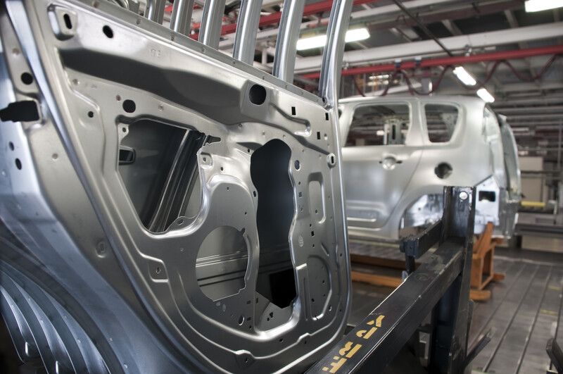
Body-in-white consists of numerous auto body components such as side structure panels, door closures panels, and subassemblies frames, forming the structures that support the vehicle and protect the driver and other passengers. There are a wide range of small features to be checked, from studs and pins to slots and threaded holes.
Different inspection processes are required at various points of production and the dimensional accuracy and precision of parts is key for optimized manufacturability. Using GD&T inspection for individual components ensures proper fitment for final assembly.
Above all challenges, a short measurement cycle time is essential to avoid creating a production bottleneck. The measurement process should ideally be situated in the shop floor environment to avoid the need to transport parts between production and the quality department. Sampling inspection of each production batch determines the acceptability of products, avoiding time-consuming 100% measurement inspection.
Ensure dimensional accuracy for downstream assembly and avoid production delays with statistical process control, combined with high-speed data acquisition for measured samples.

Our approach
Hardware Options
There are different hardware options that exist for this inspection task:
- The horizontal arm system, a type of Coordinate Measuring Machine (CMM) measuring and inspecting large BIW parts with high accuracy (single digit micron/μm).
- PartInspect L system is an automated structured light scanner that captures high-detail scan data with high-speed measurement, ideal for medium-to-large parts.
- The Absolute Arm with laser scanner is a portable articulated measuring arm with a high sampling rate to enable a fast inspection process, perfect for measuring small-to-medium size parts on the shop floor.
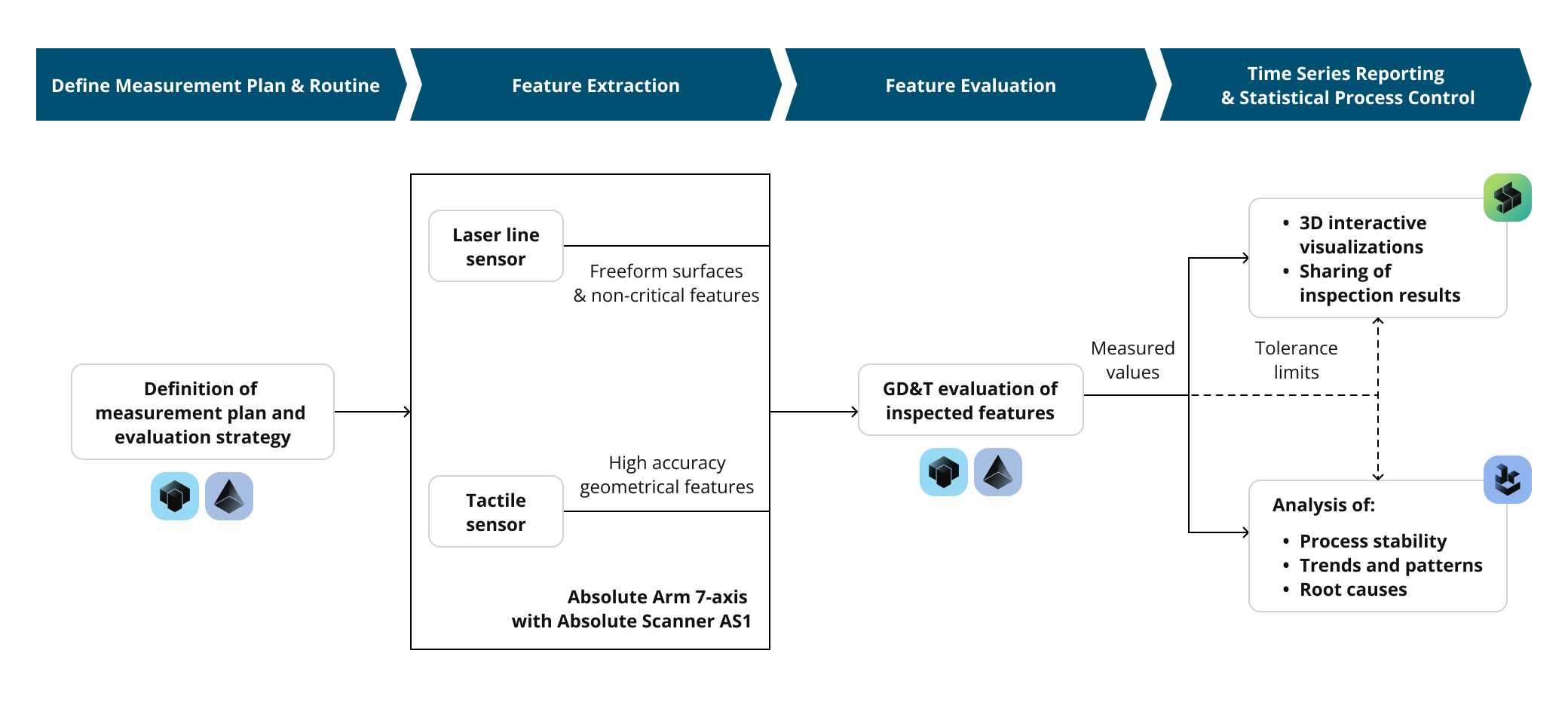
Commonly, a tactile sensor is used for high-accuracy features and a laser scanner is used for 3D surfaces and the measurement of non-critical features.
In the following, the inspection of the dashboard lower panel part is used as an example to describe the workflow. In this case, the Absolute Arm 7-axis with Absolute Scanner AS1 is the ideal hardware choice because of its portability and fast inspection method.
Define Measurement Plan & Routine
The measurement plan and GD&T inspection routine is defined in PC-DMIS measurement software. The tolerance requirement for the dimension is predefined in the measurement routine. This allows users to measure the next part component automatically by re-running the measurement plan.
Feature Extraction
A part is manually placed on the predefined position (fixture) to ensure measured features can be accessible at almost every angle of the part. In order to align the part to the CAD coordinate system, the contact sensor measures the pre-defined features of the part, followed by PC-DMIS software performing the alignment calculation.
The Absolute Scanner AS1 mounted onto the Absolute Arm scans the selected surfaces of the part and the geometry features such as circles, cylinders, studs, and slots. For such surfaces and geometries, it takes less than 90 seconds to complete the scan depending on the number of geometry features.
Feature Evaluation
PC-DMIS performs the post-processing on the extracted geometry features to evaluate the respective GD&T dimensions and tolerances. This includes evaluations of surface profiles, positions, and circular runouts. A 3D surface color map for comparison with the CAD provides an overview of which area of the part deviates from the nominal.
Visualizations and reports of the results of individual inspections can be generated in the PC-DMIS software report window. The inspection report is available in 3D graphical format with annotations on the CAD and standard report texts.
Time Series Reporting and Statistical Process Control
The inspection results can be automatically uploaded to Metrology Reporting, a cloud-based Nexus app for the management, visualization, and reporting of quality data. Metrology Reporting offers interactive visualizations of the inspection results on 3D models of the inspected parts, both for individual inspections as well as for multiple samples measured over time. The inspection results can be easily shared between metrologists, production engineers, and managers within one company, but also between suppliers and customers across different companies.
For all inspected features, the measured actual values and their tolerance limits can be transferred to Q-DAS qs-STAT for Statistical Process Control. Q-DAS qs-STAT assesses the stability of the manufacturing process based on norms, standards, and company guidelines. It identifies possible trends or patterns resulting from systematic changes in the manufacturing process early on and allows to analyze their root causes.
In Summary
This solution ensures dimensional accuracy for downstream assembly and avoids production delays with statistical process control, combined with high-speed data acquisition for measured samples.
Products
© 2026 Hexagon AB and/or its subsidiaries